I’ve wanted to build a cloud sensor for years now, but never actually found the time to do it. So, after seeing IR sensors for something on the order of $5 a piece, I ordered a couple and thought that I’d give it a shot. This has undoubtedly been done by lots of other people, but I thought that I’d share some simple instructions on how to build your own.
The theory
We could get in to the theory of blackbodies (maybe later), but it is sufficient to say that…
- Clouds are warmer than a clear sky.
- The infrared spectrum of an object can tells us something about its temperature.
- If you can measure the temperature of the sky, you should be able to say something about whether it’s cloud-free or not.
To measure the temperature we need some sort of contact-less thermometer that can be pointed at the sky (and ground, more on that later).
What you need
- 2x MLX90614 thermopile sensors
- 1x Arduino Nano
- 1x W5500 ethernet adapter
- a bunch of jumpers
- waterproof enclosure (I printed one)
- Some way to mount it over the ground
If you want to print out my housing, you’ll also need the following…
- A 3D printer (obviously) and weather-resistant filament (I use CPE/PETG)
- Silicone
- 1/4-20 nut
- tripod ball mount
When you print, you’ll want to print with supports. This design has a cupped bottom and a rounded top to, hopefully, keep some of the rain out. I printed on an Utlimaker 3 using Innofil transparent PET filament with Ultimaker breakaway for support. It worked well, but I don’t really like the UM breakaway material with the Innofil filament. Cleanup was time consuming.
Putting it together


The MLX90614 sensors ship with a fixed i2c address. 0x5A, to be exact. You can have many i2c devices on the same bus, but each must have a different address. So, you need to figure out a way to change the address on one of the sensors. Fortunately, this is fairly easy to do.
- Make sure that the SparkFun MLX90614 library is installed
- Connect one (only one) sensor to your Arduino. SDA goes to pin A4, SCL goes to A5.
- Open the MLX90614_SetAddress example
- Make sure that oldAddress is set to 0x5A and newAddress is set to 0x5B
- Upload to your Arduino
- Open a serial monitor set to 9600 baud
- Follow the instructions
- Easy, peasy, lemon squeezy.
Now that there are two different i2c addresses, both devices can be hooked up to the Arduino. At this stage I test using the following code…
//*******************************************************************************
// Reads from two MLX90614 thermometer boards and prints the object temperatures
// and the difference between the two.
//
// Modified from the MLX90614_Serial_Demo found in the library at,
//https://github.com/sparkfun/SparkFun_MLX90614_Arduino_Library
//*******************************************************************************

#include Wire.h; // I2C library, required for MLX90614
#include SparkFunMLX90614.h; // SparkFunMLX90614 Arduino library

const byte IRAddress1 = 0x5A;
const byte IRAddress2 = 0x5B;

// Create 2 IRTherm objects
IRTherm therm1;
IRTherm therm2;

void setup()
{
  Serial.begin(9600); // Initialize Serial to log output

  // Initialize the sensors and set the units
  therm1.begin(IRAddress1);
  therm1.setUnit(TEMP_C);
  therm2.begin(IRAddress2);
  therm2.setUnit(TEMP_C);
}

void loop()
{
  // Call thermx.read() to read object and ambient temperatures from the sensor.
  if (therm1.read())
  {
    Serial.print("Object 1: "); Serial.print(therm1.object()); Serial.println("*C");
  }

  if (therm2.read())
  {
    Serial.print("Object 2: "); Serial.print(therm2.object()); Serial.println("*C");
    Serial.print("Temperature Difference: "); Serial.print(therm1.object()-therm2.object()); Serial.println("*C");
  }

  Serial.println();

  delay(2000);
}

//Hardware Hookup:
//MLX90614 ------------- Arduino
//  VDD ------------------ 3.3V
//  VSS ------------------ GND
//  SDA ------------------ SDA (A4)
//  SCL ------------------ SCL (A5)
Once the two sensors are working properly, the W5500 ethernet adapter can be connected and tested. The adapter is an SPI device and can be connected as follows…
| W5500 | Arduino |
| MOSI | 11 |
| MISO | 12 |
| SCLK | 13 |
| SS | 10 |
| RST | 9 |
| 5V | 5V |
| GND | GND |
When writing the code for the W5500 adapter you’ll need to keep in mind that you want to be using the ethernet2 library. Also, these modules typically don’t come with a fixed MAC address – you’ll be setting your own in the code, so you can get creative. For this, I’d recommend choosing a ‘proper’ locally administered MAC address instead of something completely random. By proper, I mean that the least-significant bit of the first octet of the address needs to be a 1. So your address needs to look something like…
| x2:xx:xx:xx:xx:xx |
| x6:xx:xx:xx:xx:xx |
| xA:xx:xx:xx:xx:xx |
| xE:xx:xx:xx:xx:xx |
where the x’s can be hex value you want. I chose BA:D1:DE:A5 to fill my first 4 octets and use the last two to number the devices on the network. A quick google search will yield lots of interesting hex ‘words’ that you can use if you want something memorable.
The code
I’ll be the first to admit that I’m not a master coder when it comes to C/C++. I get by on the Arduino thanks to the help of the ‘Googs’ and the examples that are often provided with libraries. This project is no different. Thanks to the SparkFun MLX90614 and Ethernet2 libraries, I was able to cobble something together that works reasonably well.
What I wanted to do was simply talk to the cloud monitor every once in a while to ask for current readings and record them in a local log file. As well as creating a log, I also wanted to plot the data at regular intervals and save a PNG that could be copied to a web-accessible place for viewing.
Insert code here…
Running it
Once everything is assembled and the silicone has dried, the cloud monitor can be connected to a computer or 5V power supply through the mini-USB connector. A network cable can be connected and then you should be able either navigate to its webpage or request packets UDP packets depending on what code you’ve uploaded to the Nano.
Some results
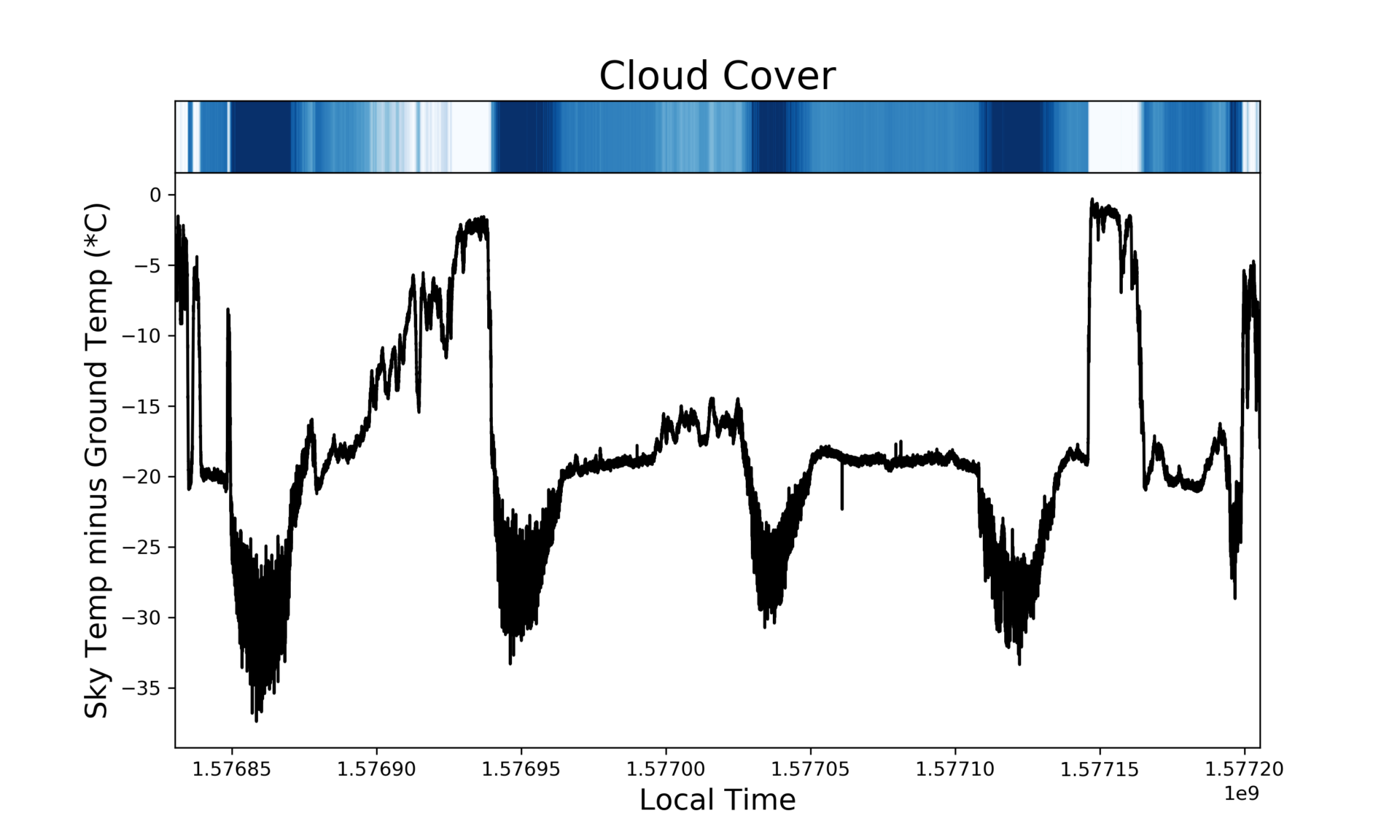
Some initial tests of the monitor show that it’s pretty good at detecting cloudy skies. The image above (several days of data) shows that, when it’s cloudy (seemingly all of the time right now), the temperature difference between the sky and ground sensor is only a few degrees. When it starts to clear up, however, the difference increases dramatically and can be up to 35 degrees during daytime clear skies. Although temperature differences of 20 degrees are a lot better than the cloudy sections, the skies are often still covered with a thin cloud.
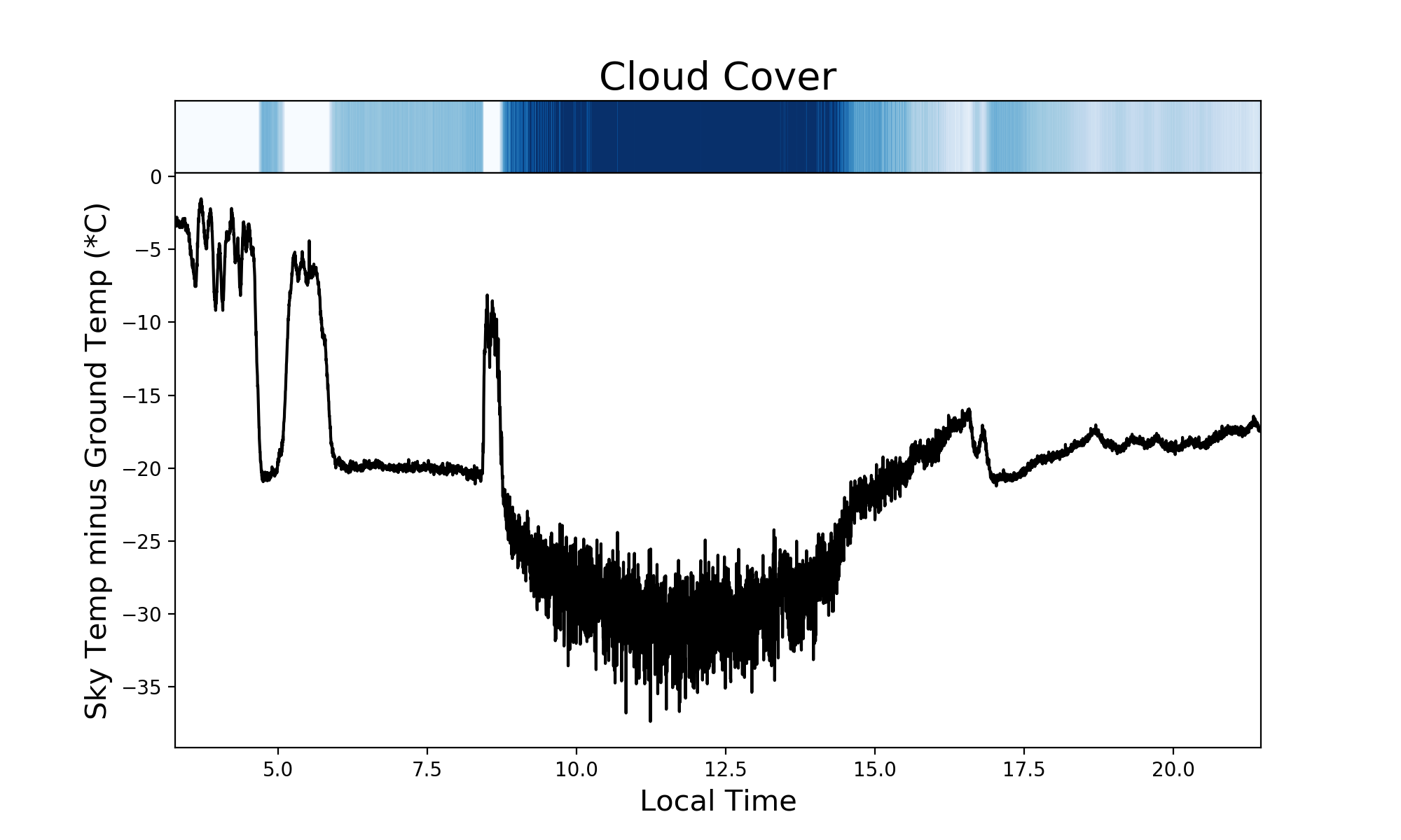
Plotting a single day of data (below) we see the typical appearance of a large, ca. 30 degree, difference during the daytime when it’s clear and ca. 20 degree differences during night time clear periods.
Coming up
I don’t like having a separate power cable for this unit, so Mark II will have POE. It turns out that it’s a pretty simple mod that I wish that I had made the first time around.