My academic work focuses on meteors. Visual (and sometimes radar) observations of faint meteors. For this, the general requirement is a sensitive video-rate camera with a moderate field-of-view. The traditional solution (after eyes, photograpic plates, vidicon, etc. ) was to use an analogue security camera with low-light sensitivity.
For many years, this was the Watec 902 series. They are good with resolutions of 720 lines on an (up to) 1/2″ CCD chip. Their sensitivity is estimated at down to levels of 0.0001 lux. And, if you wanted to kick things up a notch, you could always put an intensifier in front of it (while driving cost and complication up, of course). Great, but is it the best solution for low-light video-rate imaging? Nope.
A few years ago I was introduced to Denis Vida. We talked about meteor observations with his RMS software and whether we could use cheap IP board cameras instead of analogue cameras with frame-grabbing dongles. Since then, we’ve now tested a number of low-light CMOS cameras from Sony’s Starvis line and found that these cheap network cameras can outperform cameras costing an order of magnitude more. Sweet.
So what does this have to do with building a finder scope? Well, since a lot of my work has been with prime focus telescopes where there was no possibility for inserting an eyepiece and since we have no finder scopes, it seemed logical to take these cameras and modify them for use as a finders.
Choosing a lens
When choosing a lens you want to get as much light as possible onto the chip. Which means finding one with as large an aperture as possible. There are currently a number of very good short focal length (4-8 mm) lenses with f#’s less than 1 but most longer lenses are somewhat slower. In addition to maximizing light on the chip, you also need to consider your desired field of view. For meteor work we typically work with fields of view from about 20 degrees to all-sky. For a telescope finder, however, something narrower is desirable.
To calculate the field of view of a particular lens you only need to know its focal length (fl) and the dimensions of your chip. The IMX291 is a 1920×1080 sensor with 2.9 μm pixels. This gives a size of 5.6 mm by 3.1 mm with a diagonal of 6.4 mm. The plate scale (measured in arcseconds/mm) is given by the following,
scale = 206265/fl
The two lenses that I considered were a 25 mm f1.2 and a 50 mm f1.4. So, from the above equation I would expect the angular size of the sensor to be
(206265/(25*3600))*5.6 = 12.8 degrees in width
by
(206265/(25*3600))*3.1 = 7.1 degrees in height
for the 25 mm lens and half that (6.4×3.6 degrees) for the 50 mm lens.
What you need
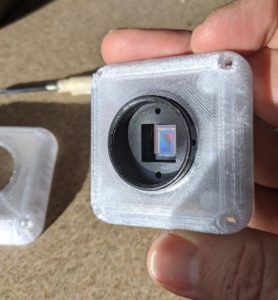
- IMX291 IP board camera
- 25 mm or 50 mm lens with a wide aperture
- POE module (or do you?)
- IP camera POE cable
- 6 1cm long M2 standoffs
- an enclosure for the camera
- POE injector
- 2 network cables
- software like CMS, ONVIF manager, Shinobi, etc.
- silicone sealant
- M2 and M3 taps
- 4 short M3 bolts for fastening the lid to the case
Putting it together
- Mount a CS mount to the camera board (be sure to peel the protective film off the chip window if there is one).
- Screw a lens into the mount and set the camera module aside
- If using my enclosure design, you’ll want to glue or silicone a 1/4-20 nut into the side of the enclosure. This allows you to attach the camera to a mounting plate/adapter for your scope.
- Next, I would open up the holes for the standoffs and run an M2 tap into them to clean up the threads
- Turn 3 or 4 standoffs into the M2 holes and then feed the IP camera cable into the enclosure
- Put the connectors on the loose wire ends
- Connect the appropriate connectors to the POE module
- Fasten the POE module to the standoffs with another round of standoffs
- Plug the POE-camera cable into the camera board
- Fasten the camera module to the exposed standoffs with the long standoffs provided with the camera module
Likely, the IP cable came without the connectors attached and may or may not have yellow and grey (or gray, if you prefer) wires. If you’re using a POE module, the cable can be connected as follows…
| Pin # | 6 pin – Data (POE) | 6 pin – Data (no POE) | 4 pin – 48V / 12V | 2 pin – 12V |
| 1 | white/blue | purple | red | red |
| 2 | blue | white/blue | black | black |
| 3 | green/white | blue | NC or yellow | |
| 4 | green | NC | NC or grey | |
| 5 | NC | white/green | ||
| 6 | purple | green |
Testing the camera
 Testing the camera is pretty straightforward. The only thing to remember is that it has likely shipped with an IP address of 192.168.1.10 or 192.168.0.10. If in doubt, you can plug it in to your router and see if a new device has shown up with a new IP address. Alternatively, you can plug it into the ethernet port on your PC, setup the networking and run arp -a and see if it shows up in the results.
For camera setup I always start with CMS as it gives me easy access to all of the camera settings. ONVIF manager gives you some control, but CMS is a better tool for setup. And if the cameras are going to be run on Linux… I recommend finding a windows machine for the setup and then switching back to Linux when running the cameras.
The basic settings that you’ll be changing are: frame rate, video format, bw/colour, AGC, and integration.
To test and setup…
- Plug in a network cable to the camera cable
- Plug the other end into the POE port on the POE injector
- Plug another cable into the LAN port of the POE injector
- Plug the other end of that cable into your PC or router
- Open up ONVIF manager or CMS and setup a new camera
- Open up the new camera
- Do you see an image? If so, focus. If not, bugger.
- If you’re using CMS, camera setup is pretty easy.
No doubt all of this can be done on Linux, but it is a bit of a pain. So we always setup our cameras under Windows before moving them onto Linux systems.
Installation
There are plenty of options for mounting the camera. You’ll need to figure out what works best for your situation, but here’s what I’ve done.
Using the finder
Since there are a number of cameras in this installation, I decided to install an application that could manage multiple cameras. Any of the finders, status cams, and security cameras can be accessed from any of the domes. Very handy. After a quick search for opensource software that would do the trick, I settled on Shinobi.
How good are they?
I guess that it depends on what is meant by ‘how good…’ They solve the problem at hand, so I consider that pretty good.
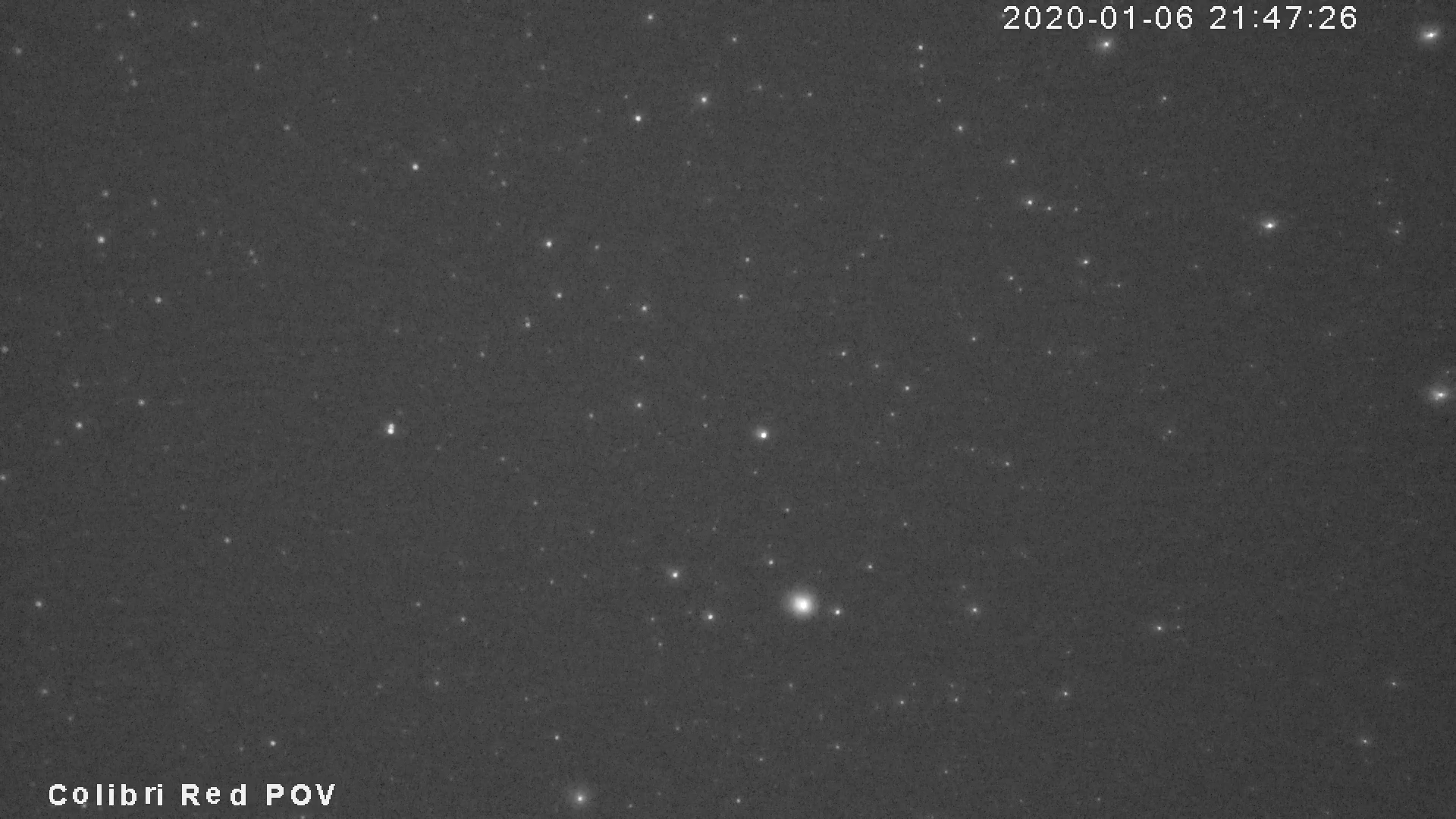
In terms that we can relate to, the limiting magnitude of the finder shown here (50 mm lens) is about M11 under dark skies. Which is pretty much what you’d expect if you were visually observing with a 2″ finder scope. To make this claim, I’ve simply taken some snapshots from the cameras and then compared them to a star map. If you really wanted to get technical, though you might want to let a computer do the work. Which I have also done.
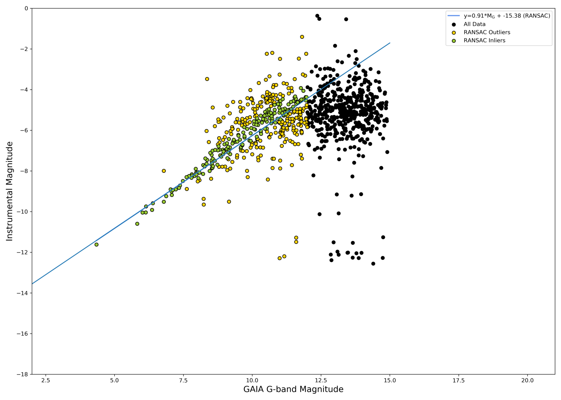
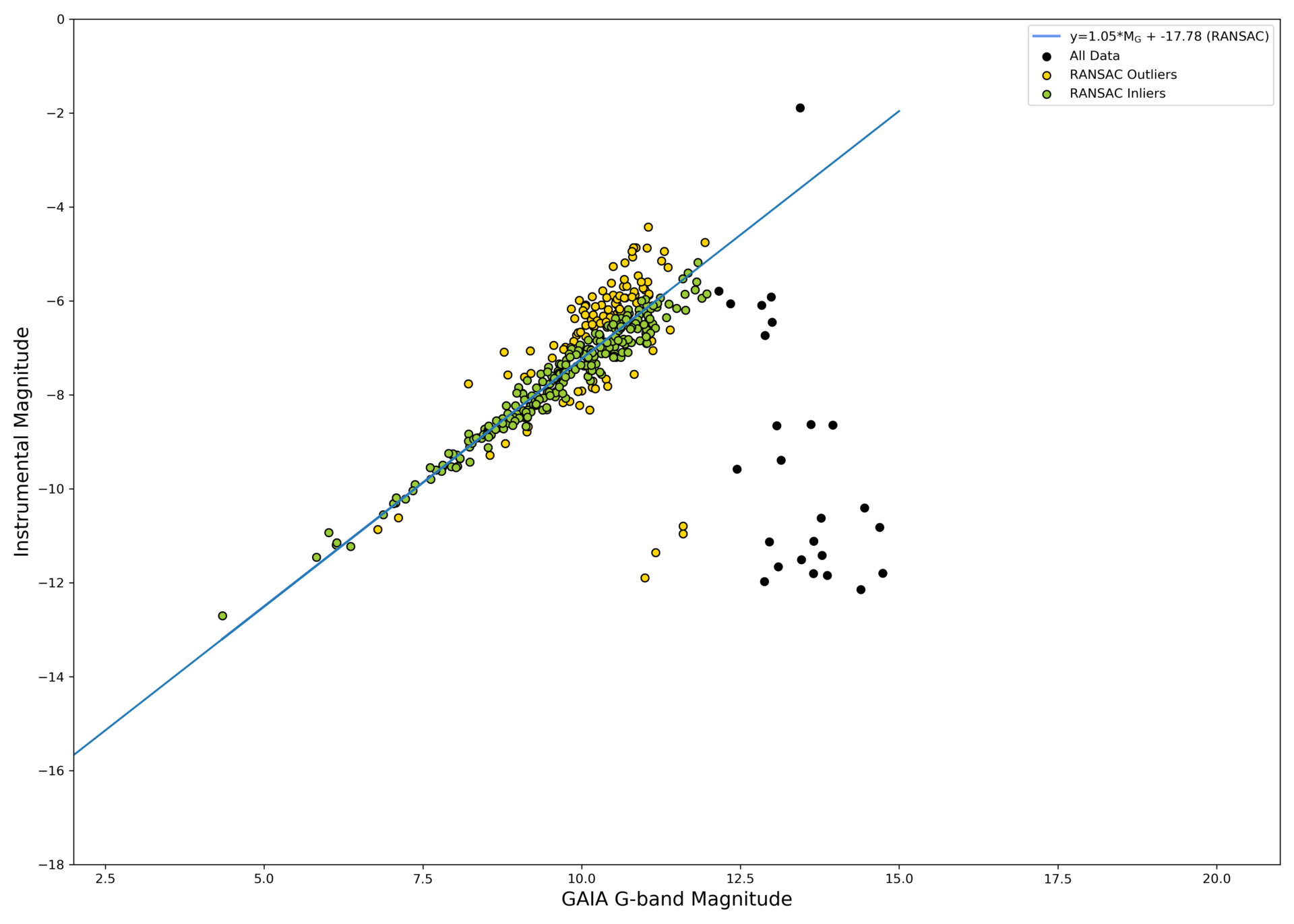
To do that, you just need to follow my instructions for a quick and dirty limiting magnitude calculation. Basically, what I do is compare detected sources in the images with real sources from the Gaia database and look for the point at which correlation drops off. The following two examples show this…
More to come…


